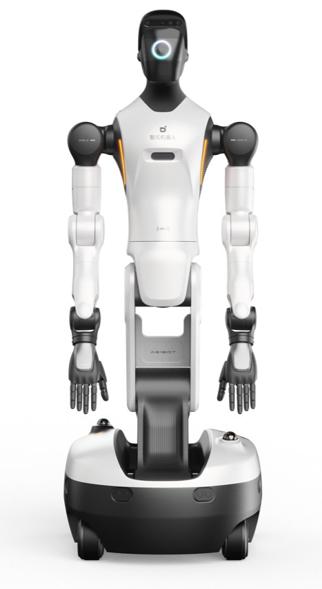
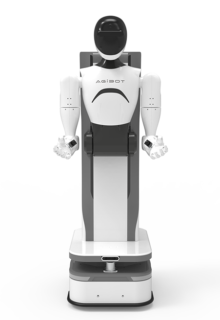
AGIBOT A3 User Manual

Release: 2026-05-08 13:41:53

Welcome to use

Thank you for choosing the AGIBOT A3 Robot.

This user manual helps you quickly get started with the AGIBOT A3 Robot (hereinafter referred to as "the Robot"), and provides detailed guidelines for operation and maintenance to ensure an optimal user experience. Should you have any problems during use, please contact our service hotline or E-mail us. Our professional technical support team will provide you with timely assistance.

Read User Manual: https://www.agibot.com/filepage/290.html


9c3c67076df64d64bdb02969d7848c15.png


Contact After-sales Service: https://www.agibot.com/filepage/292.html


93a9779260bc4cbea09af6274b8f697a.png

1.  Important Notice

1.1 Safety Guidelines

1. Know the Product: Before using the Robot for the first time, please read the manual to fully understand its functions, operating procedures, and all safety instructions.

2. Environmental Requirements: Operate the robot only on flat, dry and stable surfaces. Do not use it in environments with extreme high or low temperatures, high humidity, steep slopes, sharp drops, fragile ground or strong vibration.

3. Regular Inspection and Maintenance: Conduct regular maintenance and status checks on the Robot, focusing on key components such as joints, sensors, and the power system, to ensure the equipment remains in good working condition and to prevent safety hazards caused by component aging or damage.

4. Know the Emergency Stop Operations: Before use, familiarize yourself with the emergency stop operation method to halt the robot promptly in case of emergencies. Once the emergency stop is activated, all robot joints will lose support and collapse. For this reason, strictly observe on-site safety regulations and keep the protective frame in place at all times after an emergency stop. Do not activate the emergency stop unless necessary.

5. Reserve Operating Space: Before operation, ensure sufficient surrounding space for the robot to move. Do not use it in overly narrow areas or spaces crowded with people and obstacles, to prevent collision and pinching risks.

6. Electrical Safety: Before power-on, inspect cables, plugs and sockets to confirm they are intact and free of abnormalities. If a short circuit, overheating or other faults are detected, cut off the power supply immediately.

7. Prohibit Improper Use: Use the robot only in compliant and proper application scenarios. Do not operate it for dangerous, illegal or unauthorized purposes.

1.2 Safety Guidelines

1. Pre-Operation Checks

a. Before powering on the robot or initiating any movement, ensure no personnel, debris or obstacles remain in the working area, especially around robotic arms, joints and other moving parts, to prevent collisions and personal injury.

b. Operators shall inspect the robot for normal status before startup and confirm the completion of system self-check.

2. Standardized Operation and Training Requirements

All operating personnel must receive operating training in advance. Operators shall be familiar with the robot’s specifications, standard operating procedures and exception handling protocols, to avoid safety risks arising from improper operation.

3. Maintain a Safe Distance

Keep a minimum 1 meter safe distance from the robot’s working area during operation to prevent collision hazards caused by sudden equipment movement. Do not stay within the robot’s predicted motion path, especially during high-speed operation.

4. Prohibition of Manual Intervention During Operation

Do not manually interfere with the robot while it is running. If adjustment, maintenance or manual handling is required, confirm the robot has come to a complete stop and is fully powered off before any operation.

5. Load and Component Usage Requirements

a. Operate the robot within its rated load capacity. Do not apply loads exceeding its designed specification limits.

b. When using end-effectors, grippers and other functional components, ensure full compatibility with the target workpiece. Mismatched components may cause extrusion, abnormal stress or permanent part damage.

6. Shutdown Procedures for Abnormal Conditions

In the event of abnormalities, malfunctions or unexpected faults, immediately activate emergency shutdown via the remote control to stop all robot motions without delay.

8. Remote Control Precautions

a. If the robot is equipped with remote control functions, operate it only under stable and secure network conditions. Network interruptions, latency or external intrusion will impair control stability.

b. Remote operators shall adopt real-time monitoring measures to continuously keep track of the robot’s running status and on-site environment, so as to ensure the safety of remote operation.

2. AGIBOT A3 Overview

2.1 Unpacking List

No.

Component Name

Quantity

1

Robot Main Body

1

2

Battery Charger

1

3

Magnetic Charging Connector

1

4

Remote Control

1

5

Protective Helmet

1

6

Lavalier Microphone

1

7

Quick Start Guide

1

8

Qualification Certificate

1

9

Safety Lanyard

2

10

Lifting Rings

2

11

Silicone Hand (Fist Gesture)

2

12

Accessory Kit

1


2.2 Product Introduction

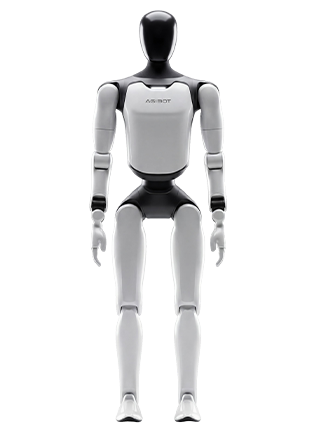
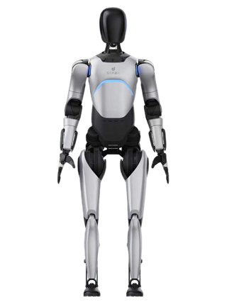
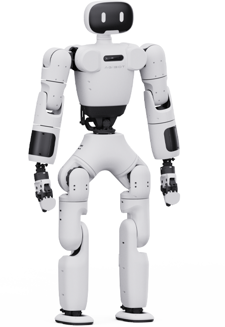
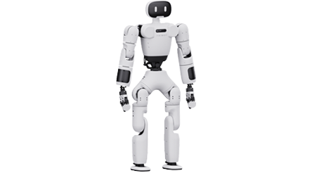
The AGIBOT A3 series products feature 31 to 57 degrees of freedom (varies by model and configuration), enabling flexible movement and high-precision posture control. The following details the specific configuration and functions of the AGIBOT A3.

The AGIBOT A3 has a total of 31 active degrees of freedom (excluding hands), with 2 in the neck, 7 per arm, 3 in the waist, and 6 per leg. It is equipped with silicone hands and silicone fists.

The perception system is equipped with RGB stereo cameras, GPS, UWB positioning, and shoulder touch sensors.

The communication system is equipped with Wi-Fi, 4G/5G mobile network, and Bluetooth.

The interaction system is equipped with omnidirectional microphones, speakers, a curved display, and omnidirectional indicator lights.

The power system is equipped with a 1152Wh battery, providing a total battery life of 10 hours, including 6 hours of standing operation and over 4 hours of continuous walking. It supports both charging and battery changing modes, with a charging time of ≤2 hours.

2.2.1 Component Names and Description

图片1.png


No.

Component

No.

Component

No.

Component

1

Head Display

7

Forearm

13

Maintenance Port

2

Left and Right Speakers

8

Hand

14

Waist

3

Interactive Binocular Camera

9

Thigh

15

Foot

4

Switch

10

Calf

16

Charging Port

5

Microphone

11

Shoulder touch sensor

17

Waist Handle

6

Upper Arm

12

Dual Battery Compartments


2.2.2 Battery Indicator 

Note: When using battery power, closely monitor the battery level. Low or nearly depleted batteries may cause the robot to topple suddenly due to insufficient power. Recharge or replace the battery immediately when only one indicator remains to maintain stable operation and avoid injury.

2.2.2.1 Location of Battery Indicator Lights

图片2.png


2.2.2.2 Indicator Status Description (Working)

Battery Light Status (Working)

Battery Level

Status Description


All LEDs off

0%

No power

LED1 on, LEDs 2-4 off

1% ≤ Battery Level < 25%

Critical Low Power (Recharge Immediately)

LEDs 1-2 on, LEDs 3-4 off

25% ≤ Battery Level < 50%

Low Power (Plan for Recharge)

LEDs 1-3 on, LED4 off

50% ≤ Battery Level < 75%

Sufficient power

LEDs 1-4 on

75% ≤ Battery Level < 100%

Full power

2.2.2.3 Indicator Status Description (Charging)

Battery Light Status (Charging)

Battery Level

Status Description

LED1 breathing, LEDs 2-4 off

Battery Level < 25%

Critical Low Power

LED1 on, LED2 breathing, LEDs 3-4 off

25% ≤ Battery Level < 50%

Low Power: Do not disconnect

LEDs 1-2 on, LED3 breathing, LED4 off

50% ≤ Battery Level < 75%

Medium Power: Operable; charge to full recommended

LEDs 1-3 on, LED4 breathing

75% ≤ Battery Level < 100%

Sufficient Power

LEDs 1-4 on

Battery Level = 100%

Charging Complete

2.2.3 User Debugging Interfaces

No.

Hardware Expansion Interface

Interface Type

Interface Description

1

Maintenance Port - Waist: For debugging and Further development

USB Type-A 2.0

Supports debugging and development of the torso MDU (RK3588)

2

Maintenance Port - Head: For debugging and Further development

USB Type-C

Supports debugging and  development of the head HDU (RK3588)

Supports connection of microphone receiver

3

Power Interface

USB Type-C

Supports 5V/3A output, and charging external devices (i.e. Remote Control)


2.3 Robot Joint Motion Range

图片3.png

Joint Name

Joint Limit

Joint Name

Joint Limit

Arm

J1 (Shoulder pitch): -170° to 170°

Waist

J1 (Waist roll): ±20°

J2 (Shoulder roll): -91° to 91°

J2 (Waist yaw): ±150°

J3 (Shoulder yaw): ±160°

J3 (Waist pitch): ±30°

J4 (Elbow pitch): -60° to 140°

Leg


J1 (Hip pitch): -168° to 154°

J5 (Wrist yaw): ±160°

J2 (Hip roll): -60° to 100°

J6 (Wrist pitch): ±93°

J3 (Hip yaw): ±158°

J7 (Wrist roll): ±33°

J4 (Knee pitch): -10° to 148°

Head

Tilt joint (Head pitch): 15° (down), 25° (up)

J5 (Ankle pitch): -52° to 30°

Rotation joint (Head yaw): ±90°

J6 (Ankle roll): ±20°

Note: Joint Limits are calculated based on structural design parameters. Individual differences may exist between devices, and these data are for reference only. 

2.4 Robot Sensor Field of View

Robot Model

Configuration

Capability

AGIBOT A3

Interactive Binocular Camera

Interactive Binocular Camera: Supports visual recognition and response in human-robot interaction scenarios

图片4.png


2.5 Robot Specifications

Robot Specifications

Details

Main Body

Height

1.73 m

Dimensions

173 cm (H) x 52 cm (W) x 30 cm (L)

Weight

55 KG

Active Degrees of Freedom

31

Neck Degrees of Freedom

2

Single Arm Degrees of Freedom

7

Waist Degrees of Freedom

3

Single Leg Degrees of Freedom

6

Perception System

3D LiDAR

/

Embodied Operation RGB-D Camera

/

Terrain Perception RGB-D Camera

/

Interactive RGB Camera

RGB Binocular Camera

Panoramic RGB Camera

/

GPS

Equipped

GPS RTK

/

UWB Positioning

Equipped

Shoulder Touch Sensors

Equipped

Communication

Communication Methods

WiFi, 4G/5G Network, Bluetooth

Interaction

Microphone

Omnidirectional Microphone

Front and Rear 8-Microphone Array

Speaker

Equipped

Face Screen

Curved Screen

Indicator Lights

Omnidirectional Indicator Lights

Performance

Knee Joint Peak Torque

320 N·m


Movement Speed

Max Daily Walking Speed: 1.8 m/s

Normal Daily Walking Speed: < 1.2 m/s

Maximum Laboratory Speed: 2.5 m/s

Max Running Speed: 5 m/s


Single Arm Payload

5 kg

Power and Energy

Battery Capacity

1152 W·h

Battery Life


10 hour

* measured with standing / walking ratio =  1:1.

* Battery life measurement is affected by walking speed and load.

Charging Methods

Supports direct charging and battery swapping

Charging Time

≤2 hour

Charging Input Voltage

110-220 V

Computing Power

Basic Computing Board

RK3588 * 2

Advanced Computing Board

/

Others

Wireless Remote Control

Equipped

OTA Update

Supported

Further Development

Supported


3. Introduction to Remote Control

3.1 Remote Control Exterior Design

图片5.png

3.2 Remote Control Button Layout

图片6.png

No.

Name

No.

Name

1

Left Trigger (L2)

8

Left Joystick (L3)

2

Left Shoulder Button (L1)

9

Back

3

Power Button

10

Home

4

Volume

11

A/B/X/Y

5

Right Trigger (R2)

12

Right Joystick (R3)

6

Right Shoulder Button (R1)

13

Start

7

D-Pad

14

Select


3.3 Remote Control Charging Instructions

Charging Method: The remote control supports charging via a USB-C cable. Do not use a high-power charger, as this may degrade the remote control's performance.

Battery Life: The remote control typically lasts about 4 hours on a single charge. A full charge takes 3-4 hours. Actual battery life is affected by various factors, and the specific duration depends on actual usage.

Precautions:

1. When using the remote control to operate the Robot, closely monitor the Robot's battery level . Low battery may prevent switching motion control modes, which could lead to the Robot falling unexpectedly.

2. Use a charger that meets safety standards to charge the remote control. It is recommended to use a 5V/1A or 5V/2A charger to prevent damage from overcharging. 


4. Usage Instructions

4.1 AimMaster Interface

4.1.1 General Guide (How to Connect the Robot)

Step 1: Language Selection (Required for First Connection)

图片7.png

Step 2: Privacy & User Agreement (Required for the first connection)

图片8.png

Step 3: Lock screen password setting (required for the first connection)

图片9.png

Step 4:Select the robot type

图片10.png

Step 5:Turn on the power

图片11.png

Step 6: Network connection (required for the first connection)

图片12.png

Step 7: Select the robot's language and location (required for the first connection)

图片13.png

Step 8: Robot authorization password (required for the first connection)

图片14.png

Step 9: Select the robot's posture

图片15.png

Step 10: Enter the home page

For detailed functionality, refer to the App User Manual https://agirobot.feishu.cn/wiki/HQTdwidb5iPBplkk9iDcpLEPnEe

图片16.png

4.2 Startup Process

4.2.1 Packaging Machine Startup

Step 1: Activate the battery

Note:

This activation step is only required when opening the package for the first time or when the battery pack is in storage and transportation mode. 

Stand the packaging box upright, open the bottom window, short press and then long press the power button of each of the two battery packs, until all the indicator lights of the battery packs light up in sequence, indicating successful activation, and then close the bottom window. 

Step 1-1: Stand up the packing box and open the bottom window

图片17.png 

Step 1-2: Activate two battery packs


图片18.png

Step 2: Open the package

Lay the packing box flat, lock the wheels at the bottom of the packing box after confirming that there are no obstacles in front, then open the top cover of the packing box and remove the middle layer and hip-cover foam, ensuring that there are no items above the robot. 

Step 2-1: Place the packing box flat

图片19.png 

Step 2-2: Lock the wheels at the bottom of the packing box

图片20.png


Step 2-3: Unlock and open the top cover of the packaging box

图片21.png 

Step 2-4: Remove the middle layer and hip-cover foam

图片22.png

Step 3: Power on and start

Press and hold the robot's power button to turn on the robot. After the robot is powered on, the head screen and the indicator light on the chest will light up.

图片23.png

Step 4: Connect to AimMaster

Complete the connection between AimMaster and the robot according to the steps in Section 4.1, and select the Packing Box startup option on the robot status page 

图片24.png

Step 5: Stand up inside the box

After confirming the environment step by step in AimMaster, control the robot to stand up from the box with one click. The robot will then enter the motion state and maintain a stable standing posture.

Note:

Ensure no obstacles are present in front of the packaging box.

Lock all casters of the box securely.

Make sure the robot’s hip position is above the red line; adjust it manually if not.

After the robot stands up, move the packaging box at least 0.5 meters away before operation.

Operation Steps

Operation Interface

Ensure the packaging box is placed steadily with no obstacles ahead

图片25.png

Confirm the box casters are locked

图片26.png

Confirm the middle layer and hip-cover foam is removed


图片27.png 

Confirm that the robot's position is correct

图片28.png

Confirm initiating the robot stand-up

图片29.png 

Robot standing up (automatic)

图片30.png

The robot successfully stands up, moves the packing box away, and ready to use

图片31.png

4.2.2  Power On in Supine Position

Step 1: Power on and start

Press and hold the robot's power button to turn on the robot. After the robot is powered on, the head screen and the indicator light on the chest will light up.

Note:

If the battery pack is in storage and transportation mode, it is necessary to activate the battery pack before powering on. The operation method is to short press and then long press the power button on the battery pack, until all the battery pack indicator lights light up sequentially. 

图片32.png

Step 2: Lay the robot flat

Lay down the robot on a flat surface as shown in the following illustration, ensuring that the entire body of the robot faces upward, its limbs are extended, and its arms are naturally placed on both sides of the body. 

图片33.png

Step 3: Connect to AimMaster

Complete the connection between AimMaster and the robot according to the steps in Section 4.1, and select the homepage entering option on the robot status page.

图片34.png

Step 4: Confirm environmental safety

Before triggering the lying-down-to-standing-up action, it is necessary to ensure that there are no foreign objects within a 1-meter radius around the robot to reserve sufficient safety space for the action execution.

Step 5: Stand up from lying flat

Under the Posture switch on the home page of AimMaster, choose "Stand" to enable the robot to stand up from a lying position. At this time, the robot enters a motion state and stands stably.

图片35.png

4.2.3 Power On in Prone Position

Step 1: Power on and start

Press and hold the robot's power button to turn on the robot. After the robot is powered on, the head screen and the indicator light on the chest will light up.

Note:

If the battery pack is in storage and transportation mode, it is necessary to activate the battery pack before powering on. The operation method is to short press and then long press the power button on the battery pack, until all the battery pack indicator lights light up sequentially. 

图片36.png

Step 2: Lay the robot face-down

Lay the robot face-down on a flat surface as shown in the illustration, ensuring that the entire body of the robot faces downward, its limbs are extended, and its arms are naturally positioned on both sides of the body. 

图片37.png

Step 3: Connect to AimMaster

Complete the connection between AimMaster and the robot according to the steps in Section 4.1, and select the homepage entering option on the robot status page.

图片38.png

Step 4: Confirm environmental safety

Before triggering the prone-to-standing action, it is necessary to ensure that there are no foreign objects within a 1-meter radius around the robot to reserve sufficient safety space for the action execution.

Step 5: Stand up from a prone position

Under the Posture switch on the home page of AimMaster, choose "Stand" to enable the robot to stand up from a lying position. At this time, the robot enters a motion state and stands stably.

图片39.png

4.3 Shutdown Process

4.3.1 Shutdown and Packing

Note:

When moving the packing box to align with the robot, be sure not to hit the robot;

Before the robot enters the packaging, confirm that all casters have been locked.

Step 1: The robot is in motion and standing stably

图片40.png

Step 2: Initiate the self-service return process

On the-page of AimMaster, choose, and start the return-to-box process after ensuring the surface is level.

图片41.png

Step 3: Move and position the packaging box

Pull out the positioning block from inside the packing box, turn it over to the outer wall of the packing box and press it firmly against the wall; move the packing box to the back of the robot so that the positioning block gently touches both legs and centers itself for positioning. 

Step 3-1: Flip out the positioning block


图片42.png 

Step3-2: Align the robot


图片43.png

Step 4: Lock the packing box

Lock all the casters of the packing box, and confirm that the inside of the packing box has been cleaned up.

图片44.png

Step 5: Robot returns to the box

After confirming  environmental safety, confirm to start entering the packaging box.

Step 6: Shut down and pack

After the robot is placed inside the packaging box, briefly press the power button on the chest, and follow the voice prompts to turn it off; then insert the positioning block, hip-cover foam, and middle layer foam back into their original positions to secure and protect the robot; finally, close the packaging box and lock it.

4.3.2 Shutdown with Supine Position

Caution: Ensure a 1-meter radius safety space around the robot to avoid collisions.

Step 1: The robot is in motion mode, use the  remote control to connect to the robot 

图片45.png

图片46.png

Step 2: Remote control the robot to lie flat

图片47.png

Step 3: Short press the power button on the chest, and follow the voice prompts to turn off the device

图片48.png

4.4 Charging and Battery Changing

4.4.1 Charging Mode

1. Charging the robot with battery installed

When both batteries are in place, the magnetic charging head of the charger can be connected to the charging port of the robot. After the power is turned on, the magnetic charging head of the charger lights up green, indicating successful charging. The schematic diagram is as follows: 

图片49.png

2. Charging the battery solely

Remove the battery and separate the magnetic adapter section of the charger to directly charge the battery. The schematic diagram is as follows: 

图片50.png

4.4.2 Battery Changing Mode 

Note:

If the battery pack is in storage and transportation mode, it is necessary to activate the battery pack before powering on. The operation method is to short press and then long press the battery pack power button until all the battery pack indicator lights light up sequentially. 

Step 1: Remove an individual battery

Step 2: Insert the "new" battery

Step 3: Repeat the above actions and replace the second battery

* Individual battery can be removed in both the shutdown state and the powered-on standing state (when only a single battery is left in place, the robot is restricted from moving)

Note:

If the battery pack is in storage and transportation mode, it is necessary to activate the battery pack before powering on. The operation method is to short press and then long press the battery pack power button until all the battery pack indicator lights light up sequentially. 


4.5 Emergency Stop Function

The emergency stop function is used for the emergency stop of the robot in case of sudden situations, preventing further damage to the robot or the surrounding environment, and can be triggered in the "software emergency stop" mode.

After the robot enters the emergency stop state, its limbs will lose power and fall to the ground, with a certain risk of damaging the machine. Please ensure that users use the emergency stop function with extreme caution.

4.5.1 Soft Emergency Stop

1. Steps to trigger the emergency stop state

Method 1: Triggered via AimMaster 

Operation Steps

Operation Interface

Press the floating ball to enter the emergency stop page

图片51.png 

Press and hold the [Emergency Stop] button, then slide it to the right until it reaches the end to trigger a soft emergency stop

 图片52.png

Enter the soft emergency stop state

图片53.png

Method 2: Triggered by remote control buttons (applicable to remote controls)

When the remote control is connected to the robot, hold the four buttons L1+L2+R1+R2 at the same time for more than 0.5 seconds to trigger the soft emergency stop state. 

图片54.png

2. Operable items in the soft emergency stop state

After the robot enters the soft emergency stop state, only limited operations such as viewing the function list, alarm information, and reporting problems can be performed on the Enmergency Stop page.

3. Steps to Exit the Soft Emergency Stop State

Restarting the robot to exit the soft emergency stop state

图片55.png

4.5.2 Emergency Stop Settings

Turn on/off the soft emergency stop function: On the [Settings] - [Movement] page of AimMaster, you can turn on and off the software emergency stop function.

图片56.png

4.6 Replace silicone hand

4.6.1 Remove Silicone Hands (use screwdriver in the accessory kit)

Step 1: Remove the silicone strip above the robot's hand to expose the screws

Before removal:

图片57.png

After removal: 

图片58.png

Step 2: Remove the four screws (two in the front and two in the back) that secure the hand

图片59.png

After removal, the hand can be detached (as shown in the figure) 

图片60.png

4.6.2 Install Silicone Hands

Step 1:Align the silicone hand with the forearm and join them together

图片61.png

Step 2:Install a total of four screws, front and rear

图片62.png

Step 3: Place the silicone strip according to the position to cover the four screws

图片62.png

4.7 Lifting Ring Installation

Step 1: Pull out the rubber plugs on both shoulders of the robot to expose the mounting slot 

图片64.png

Step 2: Hold the ring end and align the buckle end with the slot and press it firmly

图片65.png

Step 3: Rotate the lifting ring 90° and leave it there

图片66.png

5. Function Description

5.1 Full-body Dance

Select the dance content from the skill set and slide to play

Step 1: Press the [Skills] the top tab bar

图片67.png

Step 2: Select the desired dance, and slide to execute

Note: Dances need to be confirmed and executed according to pop-up instructions. Follow the tips to ensure safety.

图片68.png

5.2 Body Actions

From the skill set the user can select different actions to play.

图片69.png

5.3 Robot Interaction

1. The robot is equipped with two voice interaction inputs: Built-in Mic and External Mic, which can be switched in the voice settings on AimMaster.

2. Actions and dances can be triggered by voice commands, such as “Please shake hands” and “Give me a dance. The user needs to set up the voice interaction language on LinkSoal Platform before use voice commands.

3. Adopts a new abstract geometric expression system with dedicated designs for power‑on, idle, wake‑up, listening, speaking, working, and dancing states.

4. Additional features will be added in subsequent OTA updates. For details, refer to the release notes of each version.

5.4 LinkSoul Platform

LinkSoul Platform is a robot personality customization platform launched by AGIBOT for both enterprise and individual users. It allows you to endow the robot with unique personality and characteristics through simple and intuitive operations.

Individual Users: Can fully customize the robot’s interactive experience, including character design, personality, voice tone, knowledge base, skills, facial expressions and memory. Users can create a unique “persona” on the platform and bind it to the robot to realize an immersive interactive experience.

Enterprise Users: Can use scenario-specific intelligent agent templates (e.g., exhibition guide, healthcare companion, shopping assistant, front desk receptionist) to quickly deploy robots into business scenarios for efficient implementation and intelligent upgrading.

Detailed Usage Documentation for LinkSoul Platform:

  �� LinkSoul User Manual

图片70.png

Official website of LinkSoul Platform:

Asia: https://linksoul-sg.agibot.com/

EU: https://linksoul-eu.agibot.com/

America: https://linksoul-us-east.agibot.com/

 图片71.png

6. Accessories Management and Usage

6.1 4G/5G Module User Guide

Robots are equipped with built-in eSIM cards. For details on the specific installation and warranty services, please refer to Section 8.1 of this article.

6.1.1 SIM Card Specifications

The A3 supports Micro-SIM cards for internet access. Its cellular communication module is compatible with 4G/5G protocols. Actual network availability may vary by service provider. Please refer to your sales contact for inquiries about SIM Card support.

6.1.2 SIM Card Installation

On the neck of the device, the SIM card slot can be seen by removing the black silicone protective cover.

图片72.png

7. Daily Maintenance and Management

Compliance with the above instructions ensures safe and efficient operation of the robot. For any inquiries, please contact the manufacturer or authorized service provider for technical support.

Safety Warnings

1. Power-off Maintenance: Before any maintenance or component replacement, completely power off the device and confirm it is in a fully de-energized safe state.

2. No Unauthorized Modification: Do not modify the robot or alter its original design and configuration without official authorization.

3. Professional Repair Only: Do not disassemble the robot personally. If maintenance is required, contact the manufacturer’s designated professional service personnel.

Maintenance and Upkeep

1. Routine Maintenance: Perform regular maintenance in accordance with AGIBOT official recommendations to keep the robot in optimal operating condition.

2. Use Original Spare Parts: Only use manufacturer-specified original spare parts for component replacement to guarantee equipment performance and operational safety.

Fault Handling

1. Fault Response: Immediately stop operation once any malfunction occurs, and arrange for professional technicians to conduct inspection and repair.

2. No Unauthorized Disassembly & Repair: Do not disassemble or repair the robot by yourself, so as to prevent secondary damage to the device.

Battery and Power Management

1. Safe Charging: Do not disassemble the battery for separate charging; charge only by connecting the dedicated power supply.

2. Charging Environment: The robot’s battery shall be charged in a safe, dry environment. Avoid humid and high-temperature surroundings.

3. Prevent Overcharging: Do not keep the device connected to power for a prolonged period to avoid battery overcharging and overheating, and to prolong battery service life.

4. Professional Battery Replacement: Battery replacement must be performed only by qualified professionals. Mismatched use of chargers for different battery types may cause fire hazards.

5. Dedicated Power Supply Only: Use only the supplied removable power supply model UY600L-W546080 for charging.

6. Battery Disposal: Remove the battery and dispose of it in accordance with safety regulations before scrapping the device.

Software Management

1. Regular Software UpdatesRegularly check and upgrade the robot’s operating system and control software to fix potential vulnerabilities and enhance system security.

8. After-sales Service Policy 

8.1 Warranty Content

For details of the warranty content, please refer to https://www.agibot.com/filepage/292.html

395896ef30a9469a8f9cdbb184f750c6.png