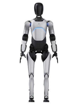
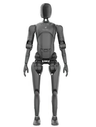
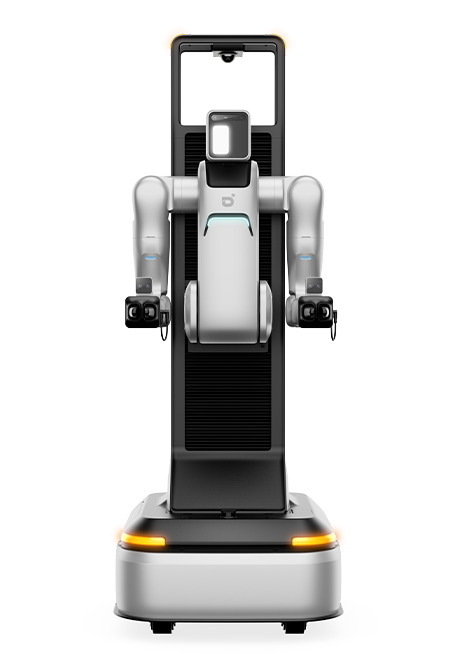
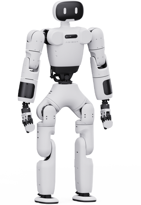
AGIBOT G2 User Manual

Release: 2026-07-30 18:04:49

AGIBOT G2 User Manual

图片1.png

This manual is for reference only. Content changes dynamically as the product evolves.

Agibot Innovation (Shanghai) Technology Co., Ltd. reserves all rights to interpret this document.


Preface

Thank you for purchasing the AGIBOT G2 wheeled humanoid robot (hereinafter referred to as the “Product”).

This product is a general-purpose wheeled-chassis humanoid robot developed by Agibot Innovation (Shanghai) Technology Co., Ltd. (hereinafter referred to as the “Company”) for industrial, commercial, cultural and entertainment, scientific research, and other industries.

Before operating or maintaining this Product, please read this manual carefully and strictly follow the instructions herein to ensure proper use of the robot and maintain its service life.

If you have any comments or suggestions, please contact us in a timely manner. We will provide you with dedicated and prompt service.

Specific operations may vary depending on the product version. This manual is for end-user reference only. The Company reserves the right to modify and interpret this manual.


Precautions

Important Safety Instructions

Before operating or maintaining this Product, be sure to read all instructions in this manual carefully and strictly comply with the relevant requirements.

Specific operations may vary depending on the product version. This manual is provided for end-user reference only. The Company reserves the right to amend and interpret the contents of this manual.

Note: Be sure to read this manual before using this Product.

Warning: Read all safety warnings and operating instructions. Failure to comply with the relevant requirements may result in electric shock, fire, or serious personal injury.

Operating Environment

1. Please ensure that the robot is used within an operating temperature range of 0°C to 45°C and at a humidity level below 90% RH.

2. Please ensure that the robot is used indoors.

Before Using the Product

1. Please check that all robot components are in good condition, with no damage or looseness.

2. Please check that the robot emergency stop button functions properly.

3. Please check whether any alarm information is displayed on the robot wireless terminal.

4. Please check whether any unauthorized accessories or devices are installed on the robot.

During Use

1. Please ensure that the robot operates within its rated load range and avoids overloading.

2. Please ensure that the end effector mounted on the robot is used correctly to avoid damage.

3. Please ensure that the robot is used on a flat surface. If the robot needs to travel up or down a slope, make sure the slope is ≤ 5%.

4. Non-professionals must not disable the robot’s active safety functions.

5. In an emergency, immediately press the emergency stop button on the robot to stop it.

6. Do not interfere with the robot’s movements while it is operating.

7. Do not touch areas on the robot surface where body parts may be easily pinched, such as the robot’s armpits, inner sides of the elbow joints, and front sides of the knee joints.

8. Do not place your feet near the robot wheels to avoid being crushed when the robot moves or rotates.

9. Do not stand between the robot and a nearby wall to avoid being squeezed when the robot moves.

10. Do not treat the robot as a toy. Pay special attention to safety when children are near the robot.

After Use

1. Store the robot in the designated location. Do not place it on a slope.

2. Turn off the robot power when it will not be used for an extended period.

Product Maintenance

1. Please perform regular maintenance on the robot according to the maintenance recommendations provided by Agibot to ensure that the robot remains in optimal working condition.

2. If the robot malfunctions during operation, stop it immediately and contact professional technicians for inspection and repair.

3. Do not perform body maintenance on the robot while it is operating.

4. Before performing body maintenance, activate the emergency stop first to ensure that the robot cannot move.

5. Before performing any circuit-related body maintenance, power off the robot first before proceeding with subsequent operations.

6. Please update the robot software version in a timely manner to prevent safety risks caused by software vulnerabilities.

7. Do not use accessories not specified by the manufacturer when replacing components.

8. Do not disassemble the product by yourself.

9. Do not modify the original design or configuration of the Product by yourself. Any modification must be authorized by the manufacturer.

10. Do not maintain the robot sensors or control system by yourself.

11. Do not charge the battery outside the Product’s operating temperature range or in an environment with excessively high humidity, to avoid battery damage or increased fire risk.

12. Do not use any charger other than the original charger supplied with the product to charge the battery.

13. Before disposing of the device, remove the battery first and recycle or dispose of the battery in a safe and compliant manner.

Product Handling

1. Turn off the robot power before handling the robot.

2. For long-distance transportation of the robot, use the official flight case or wooden crate provided by the manufacturer. During packing, properly secure the robot with wooden boards, foam, packing straps, and other protective materials. Avoid severe bumps during transportation to prevent product damage.

3. Note: The product and packaging box are heavy and may pose a pinching risk. Wear protective equipment and operate with caution when handling them.

Product Storage

1. Please store the product indoors.

2. Please store the robot within a temperature range of -20°C to 60°C.

3. Please charge the battery to full capacity every 60 days to avoid damage to battery life

4. If the product will be out of use for more than one week, ensure that the battery level is not lower than 60% before powering off the Product, and turn off the robot’s main power.


1. Product Overview


1.1 Product Introduction

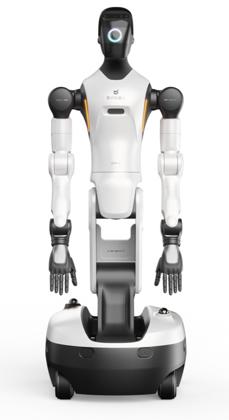
AGIBOT G2 is a general-purpose humanoid robot built to industrial-grade standards. It features outstanding motion capability, perception capability, and interaction capability, and is suitable for industrial, commercial, cultural and entertainment, scientific research, and other scenarios.

The robot is equipped with high-performance joint actuators, multiple types of sensors, and a high-performance domain controller. It supports all-scenario omnidirectional obstacle avoidance, high-precision force-controlled operation, and real-time multi-person voice interaction.

When used with additional data collection and teleoperation kits, as well as a charging doc (optional), the robot can support extended functions such as data collection, beyond-visual-range teleoperation(BVR), and autonomous recharging.

The robot also provides a wide range of SDK secondary development interfaces to support function expansion and customized development.


1.2 Functional Features

 High-Precision Force-Controlled Operation
The robot is equipped with two industrial-grade force-controlled arms. Each arm has 7 degrees of freedom and supports a payload of 5 kg. Each joint is equipped with a joint torque sensor. The robot can perform high-precision force-controlled operations, including force-controlled hole searching, insertion, and surface alignment. This design improves the robot’s operational accuracy to the sub-millimeter level, effectively expanding the application scenarios of humanoid robots.

 Highly Human-Like Operating Posture
The robot features a 3-DOF waist design and a 2-DOF foldable lifting leg design. It can accurately reproduce human waist and leg movements, enabling highly human-like complex operations with coordinated upper- and lower-body motion. When deployed in industrial and commercial environments, the robot can adapt well to work environments designed for humans, with full reachability and no blind spots. Its operating posture is highly similar to that of humans, requiring no additional environmental modifications, improving deployment efficiency while significantly reducing overall deployment costs.

 Omnidirectional Chassis Movement
The robot chassis adopts a four-wheel steering(4WS) design, supporting forward movement, backward movement, turning, and crab-walking in any direction. Crab-walking can effectively reduce the number of turns required during walking and handling, avoiding the additional time caused by acceleration and deceleration during turning, and improving overall passing efficiency. The robot chassis has a maximum speed of 1.5 m/s and a maximum obstacle-crossing height of 1.5 cm, enabling it to adapt effectively to floor conditions in various industrial and commercial scenarios.

 Intelligent Voice Interaction
The robot is equipped with a ring microphone array. Combined with 360° omnidirectional visual perception, it enbales precise target voice pickup based on face recognition and dynamic background noise cancellation. Together with the facial interaction screen and human-like whole-body movements, the robot supports multimodal intelligent emotional interaction, proactive interaction, and other functions, making it well suited for commercial guidance, front-desk reception, and emotional companionship and other scenarios.

 Low-Latency Teleoperation
The robot is optimized for low-latency teleoperation scenarios, enabling beyond-visual-range, low-latency, full-DOF single-operator teleoperation. Teleoperating the robot is like remotely operating one’s own second body, making teleoperated operations possible in real-world deployment. In addition, the teleoperation function supports one operator controlling multiple robots on a time-sharing basis, effectively addressing service scenarios with low task frequency and occasional demand.

 360° Active Safety
The robot is equipped with three fisheye cameras to form a 360° panoramic video. Together with dual LiDAR sensors at the front and rear of the chassis and eight ultrasonic sensors around the chassis, the robot provides excellent 360° perception capability with full-range coverage at long, medium, and short distances. With active safety algorithms, the robot can ensure the absolute safety of surrounding personnel and objects, providing comprehensive safety protection for human-robot collaborative operations.

 Highly Sensitive Passive Safety
The robot’s two 7-DOF force-controlled arms can detect force applied to the arm surfaces in real time. Combined with passive safety algorithms, the robot actively adjusts its motion at the moment the arms come into contact with surrounding obstacles, avoiding possible collision damage and effectively ensuring personnel safety, adding another layer of protection to overall safety.

 24/7 Continuous Operation
The robot adopts a dual-battery design and supports hot-swappable batteries quick replacement, allowing it to recover from low battery to full battery instantly for continuous operation. When used with a charging dock (optional), the robot can autonomously return to charge at low battery, enabling unattended 24/7 continuous operation.


1.3 Application Scenarios

 Logistics Handling

 High-Precision Assembly

 Exhibition Hall Guidance

 Intelligent Reception

 Security Inspection and Patrol

 Education and Scientific Research

 Interpretive Exhibitions

 Cultural and Entertainment Performances


2. Device Overview


2.1 Packing List

图片1.png

2.2 Device Components

Front and rear views of the robot body.

图片2.png


Component

Function Description

Interaction Screen

Displays facial expressions and other information, mainly used for emotional expression.

Head and Wrist RGB-D Cameras

Sensors for capturing color images and depth images.

Binocular Camera

Depth-sensing video stream sensor for teleoperation.

Fisheye Camera Array


Consists of three fisheye cameras to form a 360° surround view, used for navigation, obstacle avoidance, multi-person conversation, and other functions.

LiDAR

Two LiDAR sensors provide omnidirectional coverage and are used for navigation, obstacle avoidance, and other functions.

Ultrasonic Radar

Eight ultrasonic sensors are arranged around the chassis for short-range obstacle avoidance.

3-DOF Neck

The head supports 3-DOF movement, enabling head-pose following during beyond-visual-range teleoperation.

7-DOF Force-Controlled Arm

Human-like force-controlled arm with a rated payload of 5 kg and full-joint torque monitoring, used for high-precision force-controlled operations.

5-DOF Torso

Human-like lower-body structure supporting 3-DOF waist rotation, as well as forward/backward and vertical torso position adjustment.

Dexterous Hand (Optional)

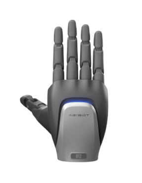
Robot end effector. Multiple types of dexterous hands and grippers are available for operating target objects.

Chassis

Four-steerable-wheel design used to drive robot movement. Supports forward movement, backward movement, in-place rotation, and crab-walking at any angle.

Emergency Stop Button

In an emergency, press this button to cut off robot joint power and stop robot movement.

Power On/Off Button

Controls robot startup and shutdown.

Power Button

Controls robot power-on and power-off status.

Battery

Two batteries, supporting hot-swappable battery replacement.

Charging Port

Used to connect the charger for charging and supports autonomous return-to-charge via the charging dock (optional).


2.3 Device Specifications

Group

Indicator

Parameter

Basic Specifications

Height

1225 mm ~ 1795 mm

Width

640 mm

Length

760 mm

Weight

185 kg

Degrees of Freedom (excluding end effectors)

25

Vertical Workspace (with O10)

0 ~ 2.3 m

Dual-Arm Reach (with O10)

2.3 m

Operating Temperature

0℃ ~ 45℃

Storage Temperature

-20℃ ~ 60℃

Operating Humidity

≤90%

Range of Motion

Head Pitch

±70°

Head Roll

±20°

Head Yaw

±30°

Waist Yaw

±174°

Waist Roll

±24°

Waist Pitch

-104° ~ 58°

Knee

0° ~ 151°

Ankle

-61° ~ 0°

Shoulder Pitch

±178°

Shoulder Roll

±120°

Shoulder Yaw

±178°

Elbow

-145° ~ 60°

Wrist Yaw

±178°

Wrist Pitch

±90°

Wrist Roll

±60°

Sensors

Head Binocular Camera

Quantity

1

Resolution

camera1: 1920 (H) * 1536 (V)camera2: 1920 (H) * 1536 (V)

Frame Rate

60 FPS

FOV

118° (H) * 92° (V)

Head Fisheye Camera

Quantity

3

Resolution

1920 (H) * 1537 (V)

Frame Rate

30 FPS

FOV

215º (H) * 170º (V)

Head RGBD Camera

Quantity

1

RGB Resolution

1280 (H) * 800 (V)

RGB Frame Rate

60 FPS

RGB FOV

94° (H) * 68° (V)

Depth Resolution

1280 (H) * 800 (V)

Depth Frame Rate

30 FPS

Depth FOV

90° (H) * 65° (V)

Wrist RGBD Camera

Quantity

2

RGB Resolution

1920 (H) * 1080 (V)

RGB Frame Rate

25 FPS

RGB FOV

105° (H) * 85° (V)

Depth Resolution

640 (H) * 480 (V)

Depth Frame Rate

25 FPS

Depth FOV

90° (H) * 70° (V)

Chassis LiDAR

Quantity

2

Minimum Detection Distance

0.1 m

Distance Measurement Accuracy (1σ)

≤2 cm (@10 m), ≤3 cm (@0.2 m)

FOV

360° (H), -7° ~ 52° (V)

Point Rate

200,000 points/s

Frame Rate

10 Hz

Chassis Ultrasonic Radar

Quantity

8

Distance Measurement Accuracy

20 mm

Detection Distance

30 ~ 3000 m

Detection Angle

100°±10° (H), 60°±10° (V)

Chassis IMU

Gyroscope Full-Temperature Zero-Bias Error

0.015 °/s (typical), 0.03 °/s (maximum)

Gyroscope Measurement Range

±250 °/s

Gyroscope Zero-Bias Stability

4 °/h (typical), 6 °/h (maximum)

Accelerometer Measurement Range

±8 g

Accelerometer Full-Temperature Zero-Bias Error

1.5 mg (typical), 2 mg (maximum)

Accelerometer Zero-Bias Stability

0.07 mg (typical), 0.1 mg (maximum)

Head Microphone

Quantity

4-microphone array

Sensitivity

-32±3.5 dB

Signal-to-Noise Ratio

70 dBA

Head Speaker

Quantity

1

Rated Power

8 W

Maximum Power

10 W

Impedance

4 Ω ± 15%

Resonant Frequency

200±20% Hz

Sensitivity

83±3 dB

Frequency Response Range

f₀ ~ 8 kHz

Head

Degrees of Freedom

3

Interactive Screen Size

6.3 inches

Interactive Screen Brightness

500 nit


Arm

Degrees of Freedom

7

Rated Payload per Arm

5 kg

Rated Payload for Dual Arms

10 kg

Peak Payload for Dual Arms

15 kg

Length

696 mm

Repeatability

±0.1 mm

Absolute Positioning Accuracy

±1 mm

Joint Torque Sensor

Supported

Force Control Resolution

≤0.02 N.m

Force Sensor Sampling Frequency

≥5 kHz

Torso

Degrees of Freedom

5

Type

Folding lift type

Waist

Supports pitch, rotation, and lateral swing

Legs

Supports folding and lifting

Chassis

Type

4 steering wheels

Maximum Speed

1.5 m/s

Pivot Turn

Supported

Crab Steering

Supported

Standard Navigation Positioning Accuracy

±5 cm, ±3°


High-Precision Navigation Positioning Accuracy

±3 cm, ±2°

Obstacle Clearance Height

1.5 cm

Climbing Capability

≤5°

Minimum Passable Width for Navigation

850 mm

Computing Platform

Standard Computing Version

Computing Power

500 TOPS (INT8)

CPU Cores

24*A78

Memory Capacity

64 GB

Storage Capacity

2T NVME SSD

High-Computing Version

Computing Power

2070 TFLOPS (FP4)

CPU Cores

14*Poseidon-AE

Memory Capacity

128 GB

Storage Capacity

2T NVME SSD

External Interfaces

Internet Port

1 Gbps

LAN Port

1 Gbps

LAN Port

10 Gbps

USB

Type-A USB 3.0 speed (low-computing version only)

USB

Type-C USB 3.0 speed

4G/5G Card Slot

Supported

Wireless Communication

Wi-Fi Network

Supported


Bluetooth

Supported

4G/5G

Optional

Power Supply


Number of Batteries

2

Total Battery Capacity

1652 Wh (34Ah)

Total Battery Life

Approx. 4 h

Rated Voltage

48 V

Rated Current

8.3A

Rated Power

Approx. 400 W

Wireless Terminal


Screen Size

11.5 inch

Screen Resolution

2000 (H) * 1200 (V)

Others

Physical Emergency Stop Button

Supported

同步自文档: https://agirobot.feishu.cn/docx/SD3bd19wwoyxspxDVL8cFihbnDJ#Z8IRdBhT8sSFB8bEbMxcDbJknOe

2.4 Interfaces

Standard Version

图片3.png 

Standard Version


Component/Interface

Function Description

SIM Card Slot

Supports 4G/5G network access.

Upper-Limb Debugging Port

Used for upper-limb debugging. For operation and maintenance personnel only.


Internet Port (1G)

Allows the robot to connect to the Internet through this port.

LAN Port (1G)

Allows the robot to connect to a local area network through this port.

LAN Port (10G)

Allows the robot to connect to a local area network through this port. This port supports 10 Gigabit Ethernet and is used for high-speed local data transmission.

DP Port

Supports connection to a monitor to display the domain controller system screen.

USB-A Port

Used to connect external devices such as a VR headset, keyboard, mouse, and speaker. It can also be used for perception device expansion, such as adding a LiDAR sensor or RGB-D camera.

USB-C Port

Same as the USB-A port.


CAUTION: When connecting the Standard Computing Version to the building’s floor or wall Ethernet outlet using a network cable, an Ethernet signal surge protective device (SPD) must be connected in series to prevent physical damage to the controller interface caused by external induced lightning strikes and transient overvoltage.

High-Computing Version

图片4.png

High-Computing Version

Component/Interface

Function Description

SIM Card Slot

Supports 4G/5G network access.

Upper-Limb Debugging Port

Used for upper-limb debugging. For operation and maintenance personnel only.


Internet Port (1G)

Allows the robot to connect to the Internet through this port.

LAN Port (1G)

Allows the robot to connect to a local area network through this port.

LAN Port (10G)

Allows the robot to connect to a local area network through this port. This port supports 10 Gigabit Ethernet and is used for high-speed local data transmission.

Debug Serial Port

Robot debugging port. For operation and maintenance personnel only.

USB-C Port

Mainly used to connect a VR headset. It also supports connection to other external devices.


2.5 Arm End Effector

End Flange

 The arm end of AGIBOT G2 uses a standard robotic arm flange end. Its mounting holes and hole layout are shown below.

图片5.png 

Communication Interface

 The AGIBOT G2 wrist is reserved with a communication connector for end effectors. The connector diameter is M8.

 The communication connector provides one 24 V power supply, two RS485 interfaces, and one CAN-FD interface.

 The connector contains 8 communication terminals. The functions of each terminal are as follows.

图片6.png 


图片7.png


CAUTION: End-effectors are NOT hot-swappable. Connect or disconnect the end-effector interface only when the robot is powered off.


3. Operation Guide


3.1 Battery Installation

1. There is a battery slot on each side of the robot chassis.

2. Insert the fully charged battery into the battery compartment. Push the battery inward as far as possible until the battery surface is flush with the robot body.

图片8.png

3.2 Device Charging

1. Make sure the battery is installed on the robot and the “Power” button at the rear of the robot chassis is turned on. The robot can then be charged.

2. Connect the power adapter to the AC power cable.

3. Plug the power cable into a power outlet, and connect the output end of the power adapter to the charging port at the rear of the robot.

 图片9.png

CAUTION: During robot charging, do not remotely control the robot to move or require the robot to perform autonomous tasks involving chassis movement, to avoid damage to the robot or charging equipment and prevent personal safety risks.


3.3 Charger Instructions

The charger supplied with AGIBOT G2 is the UY900L-W547150 charger.

图片10.png 

The basic electrical characteristics of the charger are as follows:

Group

Feature

Parameter

Output

Output Voltage

54.75 V

Output

Output Current

15 A

Output

Maximum Power

821.25 W

Input

Input Voltage

100 V–240 V

Input

Input Frequency

47–63 Hz

The charger indicator light descriptions are as follows:

Mode

Indicator Light Pattern

Status

Normal Status

Green light flashing

The charger is connected to power, but is not charging the robot.

Normal Status

Red light steady on

The robot is charging.

Normal Status

Green light steady on

The robot is fully charged.

Abnormal Status

Red light flashes 3 times, pauses, and repeats

Overvoltage protection status.

Abnormal Status

Red light flashes 5 times, pauses, and repeats

Overtemperature protection status.

Abnormal Status

Red light flashes 7 times, pauses, and repeats

Overcurrent protection or short-circuit protection status.

Abnormal Status

Red light keeps flashing

Reverse polarity protection status.


3.4 Power On/Off

The robot has two physical buttons:

 “Power” button: The “Power” button is located at the rear of the chassis. It is used to connect or disconnect power to the entire robot.

 “On/Off” button: The “On/Off” button is located on the back of the robot. It is used to turn the robot on or off.

3.4.1 Power-On Procedure

1. Press the “Power” button at the rear of the robot chassis to power on the robot. After power-on, the button lights up.

2. Press the “On/Off” button on the robot waist to turn on the robot. After the robot is turned on, the “On/Off” button lights up.

图片11.png 

3.4.2 Shutdown Procedure

1. Press and hold the “On/Off” button on the robot waist for 5 seconds, then release it. The robot enters the shutdown process and automatically shuts down after a while.

2. For long-distance transport, or if the robot will be stored in the powered-off state for more than 3 days, press the “Power” button on the robot chassis once to power off the entire robot.

图片12.png


3.5 Wireless Terminal

The wireless terminal is the main medium for users to operate the robot. The wireless terminal can be installed on the back of the robot or removed for use.

3.5.1 Device Removal and Installation

1. The wireless terminal is installed on the back of the robot when the robot is shipped from the factory.

2. Rotate the wireless terminal 90° counterclockwise to unlock the connection latch.

3. Pull the wireless terminal backward to remove it. The wireless terminal can maintain a wireless connection with the robot within a certain distance.

4. Reverse the steps above to install the wireless terminal back onto the robot.

图片13.png 

3.5.2 Connection Method

The wireless terminal automatically switches between wired and wireless connection depending on whether it is installed on the robot.

 Wired connection: When the wireless terminal is installed on the robot body, the connection mode is wired, and the robot also charges the wireless terminal.

 Wireless connection: When the wireless terminal is removed, the connection mode automatically switches to wireless. The robot connects to the wireless terminal through its own hotspot network.

3.5.3 Communication Characteristics

 Wired connection: In wired mode, the communication bandwidth is relatively low. When multiple video streams need to be played simultaneously, frame drops, lag, or other issues may occur.

 Wireless connection: Wireless connection provides relatively higher bandwidth and better smoothness when multiple video streams are played synchronously. However, in some extreme scenarios, such as exhibitions or data collection factories with a high density of robots, wireless communication may still be subject to interference, resulting in suboptimal connection performance.

3.5.4 Terminal Hardware Description

The front camera, rear camera, and SIM card function on the wireless terminal are currently disabled.


3.6 Battery Insertion and Removal

3.6.1 Battery Replacement While Powered On - Battery Hot Swapping

1. With the robot powered on, open the “Quick Menu” from the status bar on the robot’s wireless terminal.

2. In the shortcut menu, tap the Battery Replacement button to open the battery replacement screen.

3. Locate the battery to be replaced, and tap Unlock to unlock the battery.

4. Manually remove the unlocked battery.

5. Insert the replacement battery into the battery compartment. Push the battery inward as far as possible until the battery surface is flush with the robot body surface.

6. After the battery has been replaced, tap Done at the bottom of the screen to exit the battery replacement screen.

图片14.png 

图片15.png 


图片16.png 

图片17.png 


图片18.png 

图片19.png

3.6.2 Battery Replacement While Powered Off - Battery Cold Swapping

1. Pull down the white cover at the rear of the robot to open the chassis maintenance compartment.

2. Pull the rings on the upper left and right sides of the maintenance compartment to unlock the battery.

3. Manually remove the battery from the robot and replace it with a new one. Push the battery inward as far as possible until the battery surface is flush with the robot body surface.

图片20.png 

CAUTION: Do not replace the battery in this way while the robot is powered on, to avoid injury to the personnel replacing the battery.


CAUTION: Operating the robot on a single battery is currently not supported.


3.7 Basic Configuration

3.7.1  Language Switching

 The interface language of the wireless terminal can be switched by tapping “System Settings” - “Language”.

 Chinese and English are currently supported.

图片21.png 

3.7.2 Robot Wi-Fi Network Connection

1. When the robot is turned on, tap the Wi-Fi icon in the status bar of the robot wireless terminal.

2. The system automatically opens the “System Settings” app and goes to the “WLAN” page.

3. Select the network to connect to, and enter the password to connect.

图片22.png 

3.7.3 Serial Number Viewing

 Physical label: The robot serial number can be viewed on the nameplate at the rear of the robot.

 Software view: The robot serial number can be viewed on the robot wireless terminal by tapping “System Settings” - “About This Device”.

图片23.png 

3.7.4  Device Name Change

 Software view: The robot name is displayed in the upper-left corner of the robot wireless terminal.

 Name change: The robot name can be manually changed by tapping the name entry in “System Settings” - “About This Device”.

图片24.png


4. Emergency Stop

In an emergency, the robot can be stopped using either “software emergency stop” or “hardware emergency stop”.

 Software emergency stop: Stops the robot through software control and can be triggered remotely from the wireless terminal.

 Hardware emergency stop: Stops the robot by cutting off power to the actuators. This emergency stop method is more reliable.


4.1 Software Emergency Stop

1. Tap the “Software Emergency Stop” button in the upper-right corner of the robot wireless terminal to stop the robot.

2. After the robot stops, tap the button again to recover. The robot can then continue operating.

4.2 Hardware Emergency Stop

1. Press the emergency stop button next to the power button on the back of the robot to stop the robot.

2. After the robot stops, rotate the button clockwise to release the emergency stop.

图片26.png 

CAUTION: It may take several minutes to release the hardware emergency stop.


5. Software Update


5.1 Update Package Download

1. The robot upgrade package is delivered to the robot from the robot operations management platform.

2. After the robot receives the upgrade command, if the robot is connected to Wi-Fi, it will automatically start downloading the upgrade package.

3. You can view the download progress in the System Settings app on the wireless terminal.

4. The upgrade package download process does not affect normal use of the robot, and users do not need to monitor this process.

图片27.png

5.2 Software Update

1. After the upgrade package has been downloaded, an update notification will appear on the icon of the “System Settings” app.

2. Upgrade details can be viewed on the “Software” page of the “System Settings” app.

3. Tap “Update Now” to start the upgrade process. During this process, the user cannot continue to operate or control the robot, and the robot will restart during the upgrade.

4. After the update is complete, you can continue using the robot.

图片30.png 

图片30.png 

图片30.png 


CAUTION: Do not power off the robot during the update. Make sure the robot has sufficient battery power and is connected to the charger.


6. Intelligent Interaction


6.1 Voice Interaction

Open System Settings > Intelligent Conversation and turn on Intelligent Conversation. You can then speak to the robot through its built-in microphone. User-level customized services are also supported.

Before You Begin

• Network: Make sure the robot is connected to a stable network for the best experience.

• Clear Space: Before starting an intelligent interaction session, it is recommended to leave at least a 1-meter radius of free space around the robot to avoid collisions.

• Interaction Range: Speak within 3 meters of the robot for reliable voice pickup.

• Background Noise: A noisy environment may reduce recognition accuracy. Use this feature in a quiet setting whenever possible.

• Lighting: Visual recognition requires adequate lighting.

Wake the Robot

• Voice Wake-Up: Say the default wake word to activate the robot.

 Chinese: "你好,精灵"

 English: "Hi Genie"

• Gaze Wake-Up: Look at the robot for a moment, and it will greet you proactively.

• The robot is awake when you hear the audio prompt and see the listening expression.

• After waking up, the robot may move into a conversation-ready standing pose. Keep sufficient vertical safety clearance around it.

Start a Conversation

Once the robot is awake, simply say what you need. For example:

• Language Q&A: "Introduce yourself", "Tell me a joke", or "What is the tallest mountain in the world?"

• Visual Q&A: "What can you see?", "How many cups are on the table?", or "What color am I wearing?"

• English conversation: "Introduce yourself" or "Can you tell me a joke?"

Voice Skills [Beta]

• Social gestures: Say commands such as "Shake hands", "Raise your hand", "Say hello", "Nod", or "Bow" to trigger the robot's autonomous movements. This feature is available only on the new G2 model.

• Voice-Guided Navigation: Once a map and waypoints have been created in the Maps app, you can ask the robot to guide you to a saved waypoint. For example, say, "Take me to the service desk." (Supported only on V2.4.0 and later)

LinkSoul Platform [Beta]

Use the LinkSoul Platform to customize agent templates for your robot: https://linksoul.agibot.com.

• Create a custom persona.

• Customize the robot's voice.

• Build a dedicated Q&A knowledge base.

If an organization account is required, please contact the after-sales team to register and bind your robot. For more detailed operations, refer to the LinkSoul Platform User Guide.

End a Conversation

• When you finish speaking, stop and wait for a moment. No extra command is needed; the robot will exit conversation mode automatically.

• You can also end the conversation manually by saying "Goodbye" or "Exit".


6.2 Light Signals

Status

Color

Light Effect

Power-on/off successful

⚪️ Theme color (white)

Running light

Low battery (20% remaining)

�� Orange

Steady on

Charging

⚪️ Theme color (white)

Breathing light

Emergency stop

🔴 Red

Breathing light

Critical fault

🔴 Red

Flashing

Low power mode

⚪️ Theme color (white)

Steady on (50% brightness)

Default state

⚪️ Theme color (white)

Steady on

AGIBOT G2 body has 7 distributed light strips. You can intuitively understand the current operating status of the robot through light signals:


6.3 Expressions

AGIBOT G2 head is equipped with a 6.36-inch flexible display, which can show a variety of animated facial expressions. The official expression references are as follows:

Status

Expression

Power On/Off Successful

图片31.png 

Default Status

图片32.png 

Low Battery (20%)

图片33.png 

Charging

图片34.png

Fully Charged

图片35.png


Status

Expression

Emergency Stop

图片36.png

Critical Error

图片37.png

Listening

图片38.png

Thinking

图片39.png

Speaking

图片40.png

Enjoy your G2 experience. Your robot is designed to make every interaction intelligent, personalized, and engaging.


7. Motion Record and Replay

The Action Recording and Replay feature allows you to create and manage custom robot actions. Using VR teleoperation, you can record robot movements, preview the result, adjust replay settings, name and save the action, and manage saved actions later.

This feature supports recording movements for the head, arms, waist and legs, and dexterous hands. It is useful when you need the robot to save and repeat specific movements for future use.


7.1 Before You Start

Before recording an action, make sure the following conditions are met:

1. VR teleoperation has been properly set up and is working normally.

2. The connection between the robot and the VR device is stable.

3. There is enough clear space around the robot to prevent collisions during recording or replay.

4. For a more stable recording experience, a wired connection is recommended.


7.2 Recording and Playing Back Actions

7.2.1 Create a New Action

1. Go to Interaction Resource Library > Actions.

2. Click + New Action in the upper-right corner.

3. The system opens the Action Recording page, where you can start creating a new custom action.

图片41.png

7.3 Record an Action

On the Action Recording page, follow these steps:

1. Click Start Recording.

2. After the countdown ends, perform the action you want to record.

3. When the action is complete, click End to stop recording.

4. The system automatically saves the recorded motion data and takes you to the settings page.

图片42.png 

During recording, try to keep the movement smooth and complete. Avoid pausing midway or performing unrelated movements.


7.4 Configure Action Settings

After recording, you can review and configure the action before saving it.

图片43.png 

7.4.1 Action Name

Enter a name for the action. The action name is required and cannot be left blank.

Use a clear, easy-to-recognize name so you can quickly find the action later.

7.4.2 Replay Speed

You can adjust how fast the action is played back.

 Range: 0–2.0x

 Default: 1.0x

 Step: 0.1x

If the recorded movement is already fast, avoid setting the replay speed too high, as this may affect normal replay.

7.4.3 Preview

Click Preview to play back the recorded action and check the result.

Make sure the action works as expected before saving it.

7.4.4 Action Duration

The action duration shows the total length of the recorded action. This value is generated automatically and cannot be edited manually.


7.5 Save the Action

After recording and configuring the action:

1. Make sure the action name has been entered.

2. Check the replay speed and other settings.

3. Click Finish or Save.

4. The action will be saved to your action list.

Once saved, the action can be found and used from the Actions page.


7.6 Manage Saved Actions

In the action list, saved actions support the following operations:

图片44.png 

 Play: Play back a saved action.

 Edit: Change the action name, replay speed, or other settings.

 Copy: Duplicate an existing action to quickly create a similar one.

 Delete: Remove an action that is no longer needed.


7.7 Safety Notes

 Keep enough space around the robot during both recording and replay to avoid collisions.

 Make sure VR teleoperation is working properly before recording an action.

 For better recording quality, use a stable wired connection whenever possible.

 Do not press the reset button on the VR controller during recording. Doing so may interrupt the recording process.

 Keep the robot in motion during recording. Recording will fail if the robot remains stationary with no movement.

 If the recorded movement is fast, increasing the replay speed may trigger overspeed protection and prevent the action from playing correctly.

 Make sure the end effector used during replay matches the one used during recording. Otherwise, replay may fail.

 Do not play back actions when people are within the robot’s operating range.

 If an action cannot be played correctly, check the VR connection, robot status, end-effector configuration, and action settings.


8. Remote Walking


8.1 Feature Entry

1. With the robot powered on, tap “Remote Walking” on the bottom Dock of the robot wireless terminal to open the “Remote Walking” app.

2. At the bottom of the “Remote Walking” app interface, switch the walking mode using the buttons. The robot supports two walking modes: Ackermann and crab steering.

3. Use the virtual joystick to remotely control the robot's movement.

图片45.png

8.2 Button Description

Ackermann Mode

 Forward: Move the joystick to the “Forward” zone.

 Backward: Move the joystick to the “Backward” zone.

 Turning While Moving: Move the joystick to the “Forward Left Turn,” “Forward Right Turn,” “Reverse Left Turn,” or “Reverse Right Turn” zone.

 In-Place Rotation: Move the joystick to the “In-Place Left Turn” or “In-Place Right Turn” area.

图片46.png 


Crab Steering

 Forward: Move the joystick to the “Forward” zone.

 Backward: Move the joystick to the “Backward” zone.

 Diagonal Movement: Move the joystick to the “Diagonal Movement” zone.

 Lateral Movement: Move the joystick to the “Horizontal Left Movement” or “Horizontal Right Movement” zone.

图片47.png


9. Joint Control


9.1 Feature Entry

1. Tap “Joint Control” on the bottom Dock of the robot wireless terminal to open the “Joint Control” app.

2. Tap the top of the interface to switch the object to be operated, including Torso, Arm, and Actuator.

图片48.png

9.2 Step Size and Speed

1. Tap the “Step Size” setting at the bottom of the interface to adjust the robot movement step size during jog control.

2. Drag the slider at the bottom of the interface to adjust the robot speed in remote control mode.

图片49.png

9.3 Torso Control

The torso is divided into two parts: Head and Waist & Legs. Tap the up or down button corresponding to each joint to adjust the joint position.

图片50.png

9.4 Arm Control

1. Joint control is available for both arms. The control method is the same as that for the torso.

图片51.png

9.5 Posture Reset

1. Tap the Save Pose button to save the current pose to the pose list. It can be used as the target pose for reset later.

2. Tap the Manage Poses button to open the pose management screen.

3. Tap to select the target pose for reset.

4. You can manage poses created by users. System poses cannot be deleted or renamed.

5. Tap the Whole-Body Reset button. The robot will perform a whole-body pose reset using the selected target pose as the target.

图片52.png

图片53.png

10. Force Control

AGIBOT G2 is equipped with two force-controlled robotic arms, each with a payload capacity of 5 kg. Every joint of each arm is fitted with a torque sensor as standard, enabling real-time measurement of the torque applied to each joint and changes in joint torque.


10.1 Force Display

In the Joint Control app, you can view the resultant forces and torques acting on the robot’s tool center point (TCP) from the Force pannel. You can also view the external torque applied to each joint of the robot’s arms.

1. TCP 6-DOF Forces: Displays the external forces and torques acting at the TCPs of the robot’s left and right arms.

2. Joint Torques: Displays the magnitude of the external torque applied to each joint of the robot’s left and right arms.

图片54.png

10.2 Buttons

To ensure proper use of the force-control functions of the robot arms, the zero-force state is defined as the state in which the robot is unloaded—that is, an end effector is installed, but the robot is not holding any object.

In the zero-force state, the six-axis force/torque readings at the TCPs of both arms and the torque readings of all arm joints should be zero.

1. If any external force or torque reading is not zero while the robot is unloaded, tap the Zero Force Sensors button at the bottom of the screen to reset the readings to zero.

2. If an upper-body fault occurs, tap the Clear Faults button to attempt to clear the fault.

3. Force Control: A maintenance function, authorized maintenance personnel only.

4. Position Control: A maintenance function, authorized maintenance personnel only.

图片55.png

11. Navigation and Mapping


11.1 Creating a New Map

1. On the wireless terminal on the back of the robot, open the Map app.

2. If no map has been created in advance, tap Create Map to create a new map. The maximum map area should not exceed 10,000 m².

图片56.png 

3. Use the virtual joystick in the lower-left corner of the screen to remotely control the robot to move around and complete map creation.

图片57.png 

4. Tap Finish to save the map.

11.2 Map Management

1. Tap Map Management to enter the map management screen.

2. Tap a map in the map list. The map display area on the right will switch to show the details of the selected map.

3. Tap the three dots to the right of a map name in the map list to rename, delete, or perform other actions on the map.

4. Tap Edit to enter the map editing interface.

5. Tap Layers to adjust the map display content.

图片58.png

11.3 Map Editing

1. After entering the map editing page, tap Exit Editing to return to the map list page.

2. Tap Relocate to start the relocation process. See below for details.

3. Tap Waypoints to edit the waypoints on the map. See below for details.

4. Tap Virtual Wall to edit the virtual walls on the map. See below for details.

5. Tap Area to edit the areas on the map. See below for details.

图片59.png 

11.3.1 Relocation

When the robot loses localization or the user determines that the localization is incorrect, tap the “Relocalize” button to perform relocalization.

1. Tap the “Relocalize” button. An orange real-time LiDAR point cloud will appear on the map.

图片60.png 

2. Drag the robot to move it, and use the rotation slider to rotate it until the orange radar point cloud overlaps with the red map boundary.

图片61.png 

3. Tap Finish to complete relocation.

11.3.2 Edit Waypoints

1. There are two types of waypoints: Normal Waypoint and Charging Station. Select the type from the drop-down list on the left.

2. Waypoints can be created in two ways: Draw and Record.

3. In Draw mode, tap directly on the map to create a new waypoint. Drag to adjust its position, and slide the blue dot to adjust its orientation.

4. In Record mode, the software records the robot’s current position and orientation on the map.

5. Tap a waypoint in the list. The corresponding waypoint on the map on the right will be highlighted in cyan, but it will not enter editing mode.

6. Tap the three dots to the right of a waypoint name to edit, rename, or delete the waypoint.

图片62.png 

图片63.png 

11.3.3 Edit Virtual Walls

1. On the Virtual Wall page, tap continuously on the map to create a virtual wall.

2. Tap a virtual wall in the list. The corresponding virtual wall on the map on the right will be highlighted in cyan, but it will not enter editing mode.

3. Tap the three dots to the right of a virtual wall name to edit, rename, or delete the virtual wall.

图片64.png 

11.3.4 Edit Areas

1. On the Area page, tap continuously on the map to create a polygon area.

2. Tap an area in the list. The corresponding area on the map on the right will be highlighted in cyan, but it will not enter editing mode.

3. Tap the three dots to the right of an area name to edit, rename, or delete the area.

图片65.png


11.4 Autonomous Navigation

1. On the map interface, tap a blank area on the map. The “Navigate to This Location” button will appear.

2. Tap Navigate to This Location. The robot will autonomously navigate to the selected location.

3. Alternatively, you can tap an existing waypoint on the map to command the robot to navigate to that waypoint.

图片66.png

12. Teleoperation


12.1 Basic Concepts

Teleoperation

Teleoperation refers to the process in which a teleoperator uses a teleoperation device to operate the robot from a distance and complete a series of robot tasks.

图片67.png 

Data Link

During teleoperation, there are two main data links.

 Video stream: The robot compresses the captured images and video on the device side, and then transmits them to the teleoperation device through the network. The teleoperation device parses the video stream and displays it to the teleoperator.

 Control stream: The operator outputs control commands. After being processed by the teleoperation device, the commands are transmitted to the robot through the network. The robot parses the control commands and performs actions according to the commands.

图片68.png

Teleoperation Latency

 Line-of-sight teleoperation: For line-of-sight teleoperation, the user does not need the video stream returned by the robot. The user directly observes the robot’s movements with the naked eye and performs teleoperation accordingly. In this case, the data link includes only the control stream, and latency is generated only in various stages of the control stream.

 Beyond-line-of-sight teleoperation: For beyond-line-of-sight teleoperation, the user needs to first view the video stream captured by the robot, and then determine the control commands to be issued based on the image information. The control commands are transmitted through a series of processes to the robot and then executed by the robot. For beyond-line-of-sight teleoperation, control latency is generated in both the video stream and control stream links, so the overall latency is greater than that of line-of-sight teleoperation.


12.2 Teleoperation & Network Connection Methods

Depending on whether image and video streams from the robot are required during teleoperation, and on the network used, AGIBOT G2 provides multiple teleoperation methods.

Connection Method

1. No Video Transmission - Direct Ethernet Connection: Use a USB cable, which functions as an Ethernet cable, to directly connect the teleoperation device to the USB port in the robot maintenance compartment.

2. No Video Transmission - LAN: This mode is implemented by connecting both the robot and the teleoperation device to the same local area network. The LAN can be built using a wireless router, or by connecting both the robot and the teleoperation device to the same router using Ethernet cables.

3. Video Transmission - LAN: This mode is implemented by deploying a server with WebRTC capability within the LAN. The corresponding server must be purchased separately during the product purchase stage. Both the robot and the teleoperation device must be connected to this LAN.

4. Video Transmission - Public Network: The robot and the teleoperation device are both connected to the public network.

Teleoperation Mode

Connection Method

Data Transmission

Connection Credential

Credential Acquisition

No Video Transmission

Direct Ethernet Connection

UDP

None

Not required

No Video Transmission

LAN

UDP

Robot IP Address

View it on the Teleoperation page in the System Settings app on the robot HMI.

Video Transmission

LAN

LAN WebRTC

Server Address, Room ID

View them on the Teleoperation page in the System Settings app on the robot HMI.

Video Transmission

Public Network

Public-Network WebRTC

Room ID

View it on the Teleoperation page in the System Settings app on the robot HMI.

Scenario Applicability

 Data Collection Factory: Data collection factories mainly use line-of-sight collection. The two non-video-transmission solutions above are suitable for this scenario.

 Remote Operation: In remote operation scenarios, the teleoperator is far away from the robot. Factors such as data confidentiality, network deployment difficulty, network stability, and network bandwidth should be comprehensively considered when choosing whether to deploy through a local area network or use a public network link.


12.3 Teleoperation Connection

After the teleoperation mode and network connection method are determined, complete the teleoperation connection by following the steps below:

Connection Preparation

1. No video transmission - Direct Ethernet connection

a. Open the maintenance compartment on the back of the robot. There is one USB-A port and one USB-C port inside the maintenance compartment.

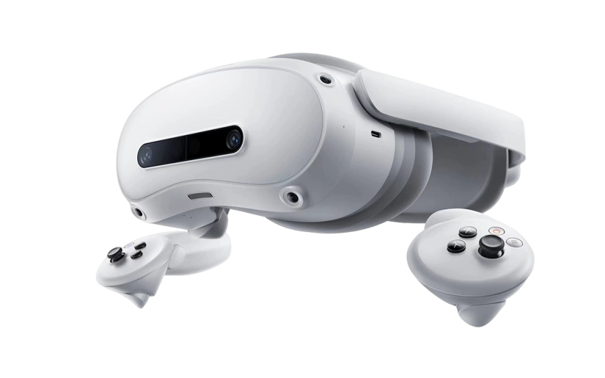
b. Connect the VR headset to the robot using the cable of the VR headset.

图片69.png 

2. No video transmission - LAN

a. Put on the VR headset and power it on. On the VR headset interface, connect the VR headset to the LAN.

b. Power on the robot. Use the robot wireless terminal to connect the robot to the same LAN.

3. With video transmission - LAN: Same as “No video transmission - LAN”.

4. With video transmission - Public network:

a. Put on the VR headset and power it on. Connect the VR headset to the public network in the VR headset.

b. Power on the robot. Use the robot wireless terminal to connect the robot to the public network environment.

Network Requirements

 Bandwidth Requirements: For video transmission mode, sufficient network bandwidth must be ensured whether the robot is connected through a LAN or the public network.

 The recommended bandwidth is 20 Mb/s per robot.

 Please ensure that the total bandwidth meets the requirements for robot teleoperation, make sure the wireless network signal strength at the robot side is normal, and avoid connecting other devices to the same wireless network to prevent network congestion.

 Teleoperation Exceptions: When the network bandwidth is insufficient or the network signal strength is low, exceptions such as video stream lag, audio stream lag, unsmooth robot movement, or teleoperation disconnection may occur.

Establish Connection

1. Open the Genie Link app in VR.

2. On the connection screen of Genie Link, select the corresponding configuration based on the teleoperation mode and network connection type, and enter the required parameters according to the information displayed on the robot wireless terminal.

3. Tap the Connect button. When the Connection Successful pop-up message appears, the connection has been established.

图片70.png 

图片71.png 


12.4 Teleoperated Robot

No video transmission

In no video transmission mode, after the connection is successfully established, the connection screen will show that the robot is connected. You can then remove the headset and place it around your neck, observe the robot’s movements directly with your eyes, and control the robot using the VR controllers.

With video transmission

In video transmission mode, after the connection is successfully established, the connection screen will disappear and be replaced by the robot video stream screen. The teleoperator can observe the robot’s surrounding environment through the video stream screen and operate the robot using the VR controllers.

With video transmission

图片72.png 


Teleoperation Control Mode Description

To adapt to different operation requirements and physical space constraints, two control modes are provided: Absolute Mode and Relative Mode. The operator can switch between the modes with one tap on the system interface, and the switch takes effect immediately.

Absolute Mode

1. Function Description Absolute Mode provides 1:1 real-space mapping. In this mode, the position and posture of the VR controller in physical space are fully synchronized to the robot. The system locks the absolute spatial coordinate system between the controller and the robot end effector(like gripper). The operator can control the robot as if directly moving their own arms.

2. Applicable Scenarios This mode is suitable for scenarios where the robot needs to accurately map the operator’s movements in real time. For example: high-precision trajectory teaching during data collection.

3. Operation Steps: In the VR interface or operating terminal, tap to select [Absolute Mode].

4. Pose Initialization: Hold the controllers with both hands and keep them consistent with the robot’s reset initial position.

Relative Mode

1. Function Description Relative Mode uses displacement increment control, with an operating principle similar to that of a computer mouse. When the operator’s operating space is limited, or when the robot needs to perform large-range movement, the robot’s working range can be extended indefinitely by “pressing and holding the button to establish the connection and releasing the button to disconnect the connection.”

2. Applicable Scenarios This mode is suitable for scenarios where the target is far away, large-span movement is required, or the operator’s own physical activity space is limited. For example: controlling the robot arm for long-distance operation.

3. Operation Steps: In the VR interface or operating terminal, tap to select [Relative Mode].

4. Takeover and Movement: Press and hold the designated clutch button on the controller, namely the side grip button. At this point, the controller establishes a control connection with the robot. Move the controller, and the robot will move according to the movement direction and speed of the controller.

5. Disconnection and Reset (Key Operation): When the controller is about to move out of the operator’s comfortable range or physical boundary, release the clutch button. At this point, the robot will remain in place and stay still. You may also tap the reset button to perform reset.


Mode Switching Recommendations

 When performing a complete task, it is recommended to use the two modes in combination.

 Step 1: Enable [Relative Mode] to move the robot quickly over a large range to the target work area.

 Step 2: Switch to [Absolute Mode] and use the 1:1 precise fine-control capability to complete the final grasping or assembly action.

WARNING

During teleoperation, do not intentionally shake the robot at high speed, in the opposite direction, or at high frequency, to prevent the robot from tipping over and causing property damage or personal injury.


13. Data Collection


13.1 Online Collection

Online collection is suitable for scenarios with large data collection volumes, high data quality requirements, and network connectivity. On-device HMI and the cloud-based Genie Data platform (separate purchase required) are used together to complete real-robot data collection. The data collection process is as follows:

图片73.png 


13.1.1 Collection Settings

Enter the domain name and tenant. If you are not sure of the relevant information, contact the on-site delivery personnel for confirmation.

图片74.png

13.1.2 User Login

Log in to the data collection module using a Genie Data account with the Data Collector role. Other modules can be accessed without logging in.

图片75.png

13.1.3 Claim Task

1. After logging in, enter the Task Center list page. On this page, users can view the task name, task purpose, task requirements, end-effector type, collection mode, and other information.

图片76.png

2. In Task Notes, tap “View” to view the detailed task description.

3. In the Operation column, tap “Enter” to go to the action list page. This page lists all actions under the task, including the duration requirement and action difficulty of each action. The “Personal Collection Progress” section specifies the number of repeated collections required for the action and the number currently completed.

4. In the Operation column, tap “Claim” to claim the task. After the task is claimed, the corresponding option in the Operation column changes to “Collect”.

图片77.png

13.1.4 Data Collection

1. Tap “Collect” to enter the Start Data Collection page.

a. Camera View: View the placement of objects and whether the end effector is in the correct position through the head and wrist cameras.

b. Whole-Body Control: Adjust the robot posture.

c. Reset Posture: Restore the robot to the preset posture.

d. Exit Collection: Return to the action list.

e. Historical Data: View historical data, data upload progress, and review results.

f. Start Collection: Start collecting data.

图片78.png

2. Tap “Start Collection”. The countdown starts, and the collector remotely operates the robot according to the task requirements. The action must be completed within the specified time. During the process, the collector can tap “Abandon Collection” to cancel the collection and return to the Start Collection page.

3. After completing the required action, tap “Complete Collection”.

图片79.png

4. After the verification is passed, tap “Submit and Continue” to upload the data to Genie Data and start collecting the next data entry.

图片80.png


13.2  Offline Collection

13.2.1 Applicable Scenarios

Offline collection operations are completed entirely on the HMI. This mode is suitable for the following scenarios:

 Users with a small data collection volume who have purchased only the robot body.

 Collection sites without network access, where offline data is exported after collection and uploaded to the data platform.

13.2.2 Operation Guide

No account or password is required. Tap the “Offline Collection” button.

图片81.png

Enter the offline collection task list.

图片82.png

Tap “New Task” to create an offline collection task.

图片83.png

After the task is created, tap “Start Collection” in the Operation column of the corresponding task. On the Start Collection page, check whether the camera view meets the requirements. You can adjust the robot posture through Whole-Body Control.

图片84.png 

Tap “Start Collection”. After the countdown ends, start teleoperating the robot to collect data.

图片85.png 

After collection is complete, tap the “Complete Collection” button to go to the completion page. Based on the data verification result, you can choose to discard or submit the data.

图片86.png

In the Task Center, you can view the number of collected data entries in the data count list item.

图片87.png

Tap the value to go to the dataset page. File names can be modified.

图片88.png 

Tap “Export” to export the collected files to an external storage device.

图片89.png

Due to the limited local storage space of the robot, it is recommended to promptly delete data that has been successfully exported to an external storage device.

The current version does not support hot swapping of USB drives. For the USB drive mounting method, refer to:SSD 支持热拔插功能.pdf


14. Developer Tools


14.1 Feature Entry

On the desktop of the robot wireless terminal, tap “Developer Tools” to open the “Developer Tools” app.


14.2 Version Description

 Offline version: Supports viewing the robot’s local SDK documentation.

 Online version: Accesses the latest online SDK documentation through the network. The online version also provides enhanced functions such as intelligent customer service.

图片90.png


14.3 Connection Guide

The online version must be accessed by connecting to the robot. Both wired and wireless connection methods are supported.

1. Tap Connect: Tap the “Connect” button. The system will prompt you to perform security authorization.

2. Switch browser mode: Due to security protocol requirements, manually switch the browser to “Insecure Mode”.

3. Log in again: After the switch is successful, tap “Connect” again and complete login.

图片91.png 

CAUTION: If the browser mode is not switched, the connection may be blocked by the firewall.


14.4 Feature Usage

After the connection is successful, you can:

 Document Query: Browse the complete SDK API descriptions and development examples.

 Intelligent Customer Service: Ask questions and receive real-time answers directly through intelligent customer service.

图片92.png

15. Maintenance and Cleaning Requirements


15.1 Personnel, Equipment, and Environmental Requirements

 Routine cleaning and inspection shall be performed by trained operators. Mechanical and electrical maintenance shall be performed only by AgiBot-authorized technicians.

 Use a soft lint-free cloth and neutral cleaning agent. Alcohol-containing or corrosive cleaning agents are prohibited. Replacement parts must be genuine original parts.

 Before cleaning, press the Emergency Stop button. Disconnect the power supply before performing any maintenance involving electrical circuits.

 Operate the robot indoors on a flat, dry surface at an ambient temperature of 0°C to 45°C and relative humidity of no more than 90% RH. 


15.2 Maintenance Schedule

Regular maintenance can extend the service life of the robot and reduce safety risks. The maintenance intervals may be adjusted as appropriate according to the operating environment and frequency of use.

Component

Maintenance Task

Weekly

Monthly

Annually

Interactive screen and camera lenses

Wipe clean and check for dirt, contamination, or obstruction

Once


LiDAR window

Wipe clean and ensure an unobstructed field of view

Once


Ultrasonic sensors

Wipe the sensor surfaces

Once


Drive wheels and chassis

Remove entangled objects and accumulated dust


Once


Force-controlled arm

Check joint movement and wipe the surface


Once


Dexterous hand / end effector

Check opening and closing operation; remove any residue


Once


Emergency Stop button

Perform a functional test


Once


Battery

Inspect appearance and check battery level


Once


Charging port / charging dock (optional)

Remove entangled objects and accumulated dust


Once


Fasteners

Check for loose screws or fasteners


Once

Robot body

Comprehensive inspection by authorized after-sales service personnel


Once


15.3 Cleaning Methods

 Lenses/screens: Use a dry lint-free cloth and wipe gently from the center outward. For stubborn stains, apply cleaning agent to the cloth before wiping. Do not spray liquid directly onto the surface.

 Radar sensors: Gently wipe the sensor window with a dry cloth and ensure that the field of view is unobstructed. Do not disassemble the sensor.

 Robot body/chassis: Wipe using a cloth dampened with neutral cleaning agent. Remove any objects entangled around the wheels. Confirm that all cleaned surfaces are dry after cleaning.

 Charging contacts: Check for dust or foreign objects. Use an insulating plastic stick or similar non-conductive tool for cleaning.

Before cleaning, press the Emergency Stop button. Do not clean the robot while it is operating. Stop operation immediately and contact AgiBot After-Sales Service if any abnormal condition is identified.


15.4 Battery Care

 Stop using the battery immediately and replace it if swelling, leakage, or physical damage is observed.

 Regularly inspect the battery housing and connectors to ensure that they are free from contamination, corrosion, or looseness.

 When the robot will be out of service for more than 7 days, ensure that the battery level is at least 60%, then power off the robot for storage.

 Charge the battery to full capacity every 60 days to avoid reduced battery life.

 Use only the original charger. The use of non-original chargers is prohibited. 


15.5 Spare Parts and Consumables

Item

Purpose

Lint-free cloth

Cleaning lenses, screens, and the robot body

Neutral cleaning agent

Cleaning robot exterior surfaces

Original battery

Battery replacement / replacement of aged batteries


Appendix

I. Device Open Port

Serial Number

Port Number

Does this port need to be opened?

Function


1

22

Yes

Provides secure remote access (SSH) for system maintenance, debugging, and operation

2

80

Yes

Provides HTTP service for Web UI, API gateway, or static resource access

3

111

Yes

rpcbind service required for NFS-related file system communication

4

20048

Yes

NFS mount service for remote file system access and data mounting

5

2049

Yes

Core NFS service for file sharing, log upload, and data storage

6

32765

Yes

NFS status monitoring service (rpc.statd)

7

32767

Yes

NFS file locking service (lockd)

8

7000

Yes

Core motion control communication interface for robot actuation and debugging

9

7001

Yes

Secondary motion control communication interface

10

8765

Yes

Data link service for data streaming, collection, and feedback

11

8766

Yes

Data link service for data streaming, collection, and feedback

12

8849

Yes

SDK HTTP interface for secondary development and external integration

13

8850

Yes

SDK HTTP interface for secondary development and external integration

14

12345

Yes

Temporary or non-standard service port, recommended for removal

15

11811

Yes

Device discovery service (DDS discovery / LAN broadcast)

16

2379

Yes

Core middleware/configuration service (e.g., etcd-like service)

17

25620

Yes

External device interface (e.g., VR/Pico connection)

18

32012

Yes

Edge/cloud communication interface

19

8761

Yes

OTA update service interface for system upgrade

II. Data Collection Format Specification

[G02 Offline Data Collection Format Specification - rb235-EN.pdf]

III. Radio Frequency Specifications

Specifications

2.4GHz Wi-Fi: 20dBm (EIRP)

Bluetooth: 20dBm (EIRP)

5GHz Wi-Fi:

5150-5250MHz: 23dBm (EIRP)

5725-5850MHz: 14dBm (EIRP)

Wi-Fi 5150-5250MHz frequency range is limited to indoor use in all EU/EFTA member states and Turkey.

Cellular bands

LTE Band 1: Uplink: 1920-1980MHz, Downlink: 2110-2170MHz

LTE Band 3: Uplink: 1710-1785MHz, Downlink: 1805-1880MHz

LTE Band 7: Uplink: 2500-2570MHz, Downlink: 2620-2690MHz

LTE Band 8: Uplink: 880-915MHz, Downlink: 925-960MHz

LTE Band 20: Uplink: 832-862MHz, Downlink: 791-821MHz

LTE Band 28: Uplink: 703-748 MHz, Downlink: 758-803MHz

LTE Band 32: Downlink only: 1452-1496MHz

LTE Band 34: Uplink & Downlink : 2010-2025MHz

LTE Band 38: Uplink & Downlink : 2570-2620MHz

LTE Band 40: Uplink & Downlink : 2300-2400MHz

LTE Band 41: Uplink & Downlink : 2496-2690MHz

LTE Band 42: Uplink & Downlink : 3400-3600MHz

LTE Band 43: Uplink & Downlink : 3600-3800MHz

LTE Band 46: Downlink only: 5150-5925MHz

5G NR:

NR n1: Uplink 1920-1980MHz, Downlink 2110-2170MHz

NR n3: Uplink 1710-1785MHz, Downlink 1805-1880MHz

NR n7: Uplink 2500-2570 MHz, Downlink 2620-2690 MHz

NR n8: Uplink 880-915 MHz,925-960 MHz Downlink

NR n20: Uplink 832-862 MHz,791-821 MHz Downlink

NR n28: Uplink 703-748 MHz,758-803 MHz Downlink

NR n38: Uplink & Downlink: 2570-2620MHz

NR n40: Uplink & Downlink: 2300-2400MHz

NR n41: Uplink & Downlink: 2496-2690MHz

NR n75: Downlink only: 1432-1517MHz

NR n76: Downlink only: 1427-1432MHz

NR n77: Uplink & Downlink: 3300-4200 MHz

NR n78: Uplink & Downlink: 3300-3800 MHz


LTE bands: 23dBm+2.0dB/-2.0dB

5G NR: 23dBm +2.0dB/-2.0dB (Power class 3, NR band n1/3/7/8/20/28/38/40)

26dBm +3dB/-4dB (Power class 2, NR band n41/77/78)


RF exposure:

The equipment complies with radiation exposure limits set for an uncontrolled

environment. To avoid the possibility of exceeding radio frequency exposure

limits, human proximity to the antenna shall not be less than 20 cm during normal

operation. This transmitter must not be co-located or operated in conjunction with any

other antenna or transmitter.